Pressure Sensor
- Analog transducer with 0.5–4.5 V output
- Read via ADC with averaging filter
- Converted to MPa/psi for control & display
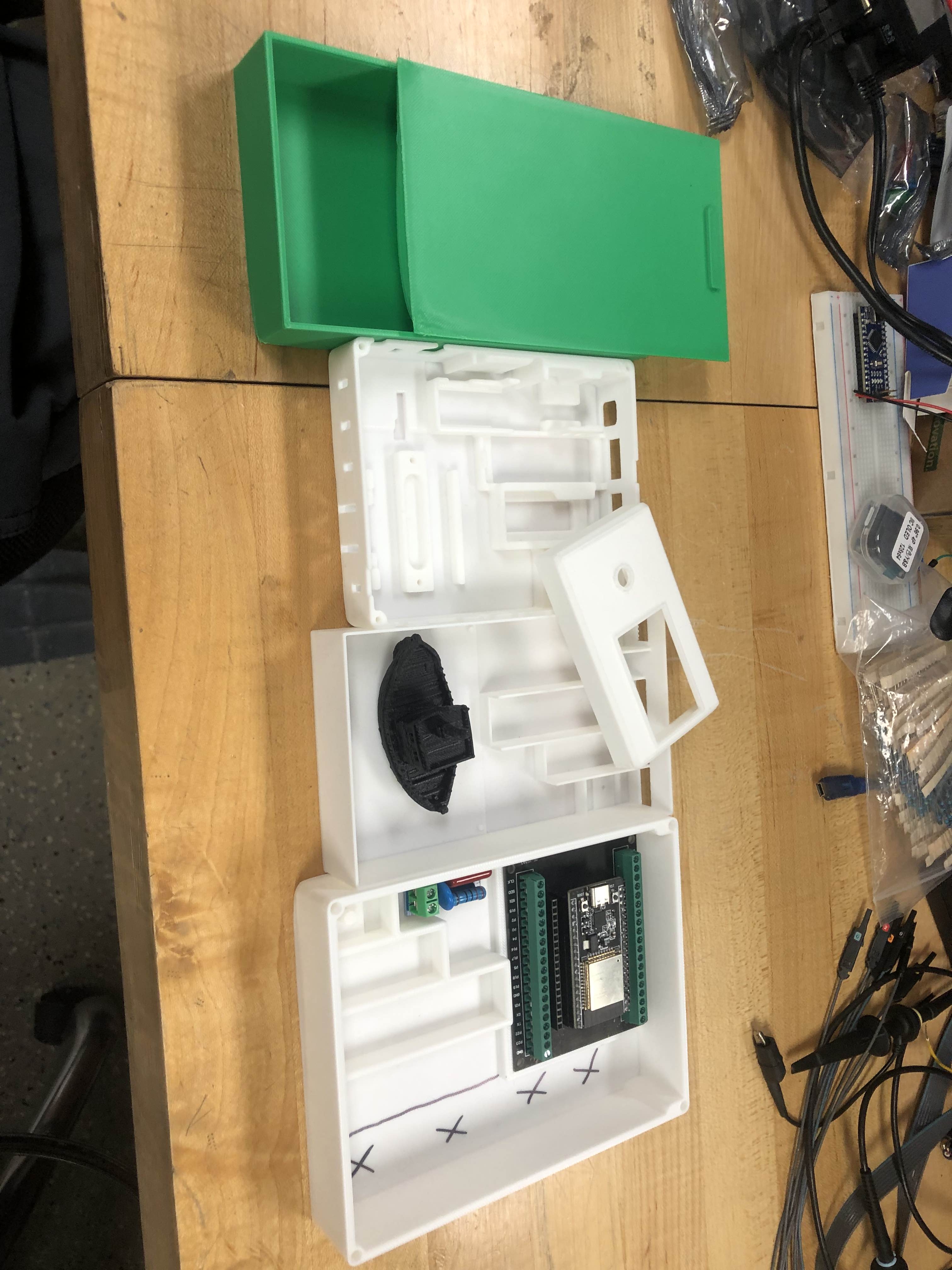
Overview of the physical components used in the system: display, sensors, control electronics, and the ESP32. This page also lists the wiring and pin mappings used in our prototype.
We use a 128×64 OLED (SSD1306) connected via I²C to present real-time temperature and pressure, along with the on-device menu controlled by a rotary encoder.
Computes control output in 0–100 % based on error to setpoint.
Maps PID output to a duty cycle (0–100 %) to regulate the heater.
Switches the heater according to PWM, providing isolated on/off control for AC load.
Phase-Skip Modulation with zero-cross detection adjusts effective AC power to the pump, enabling indirect pressure control.
ESP32 runs the dual-loop control, sensor sampling/filtering, OLED UI, rotary encoder input, PWM generation (MCPWM), and the PSM dimmer interface.
Two-box design: Interface box (OLED + rotary encoder) and Components box (ESP32, SSR/triac, sensors). Inspired by Gaggiuino; printed in PETG with M3 heat-set inserts.