Sensor Install
While installing the sensors it may be helpful to unscrew the boiler. Unscrew the 4 main bolts holding the boiler from under the group head. This can allow just enough movement of the boiler to reach the hoses and fittings more easily. Be careful not to stretch wires and hoses while doing this.
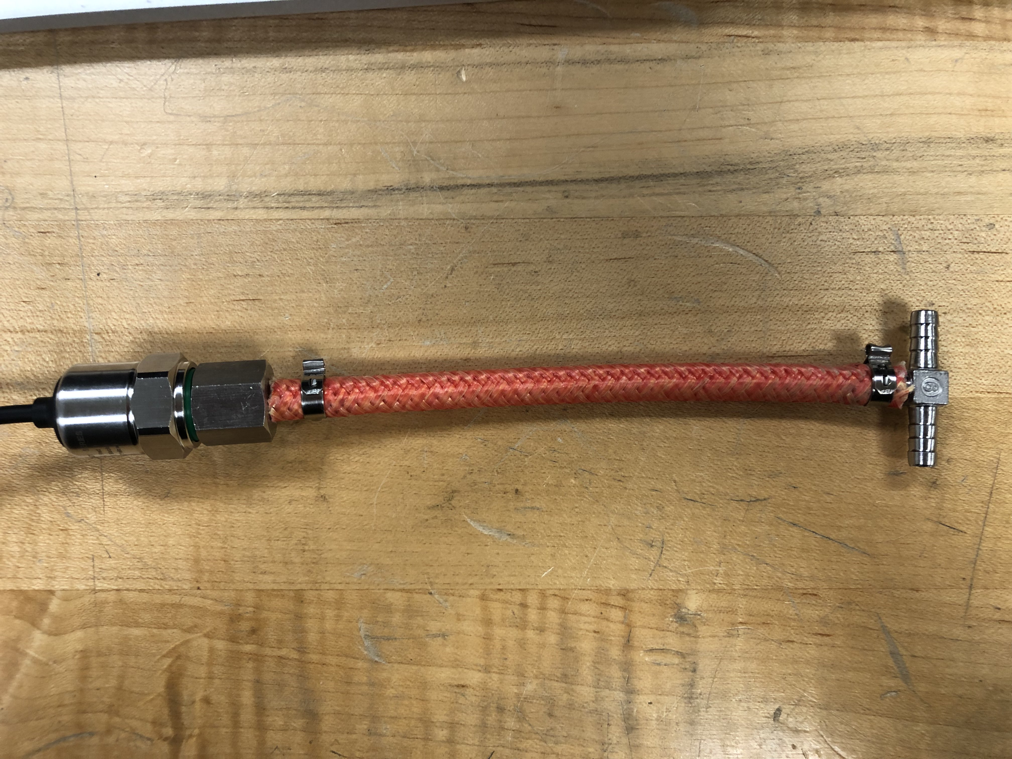
Pressure Sensor
The pressure sensor is installed in line between the pump and the boiler. Cut a few inch long section of the new high pressure tubing and crimp the T-fitting on one side and the pressure sensor adapter on the other. Use the adapter with a gasket inside to screw on the pressure sensor.
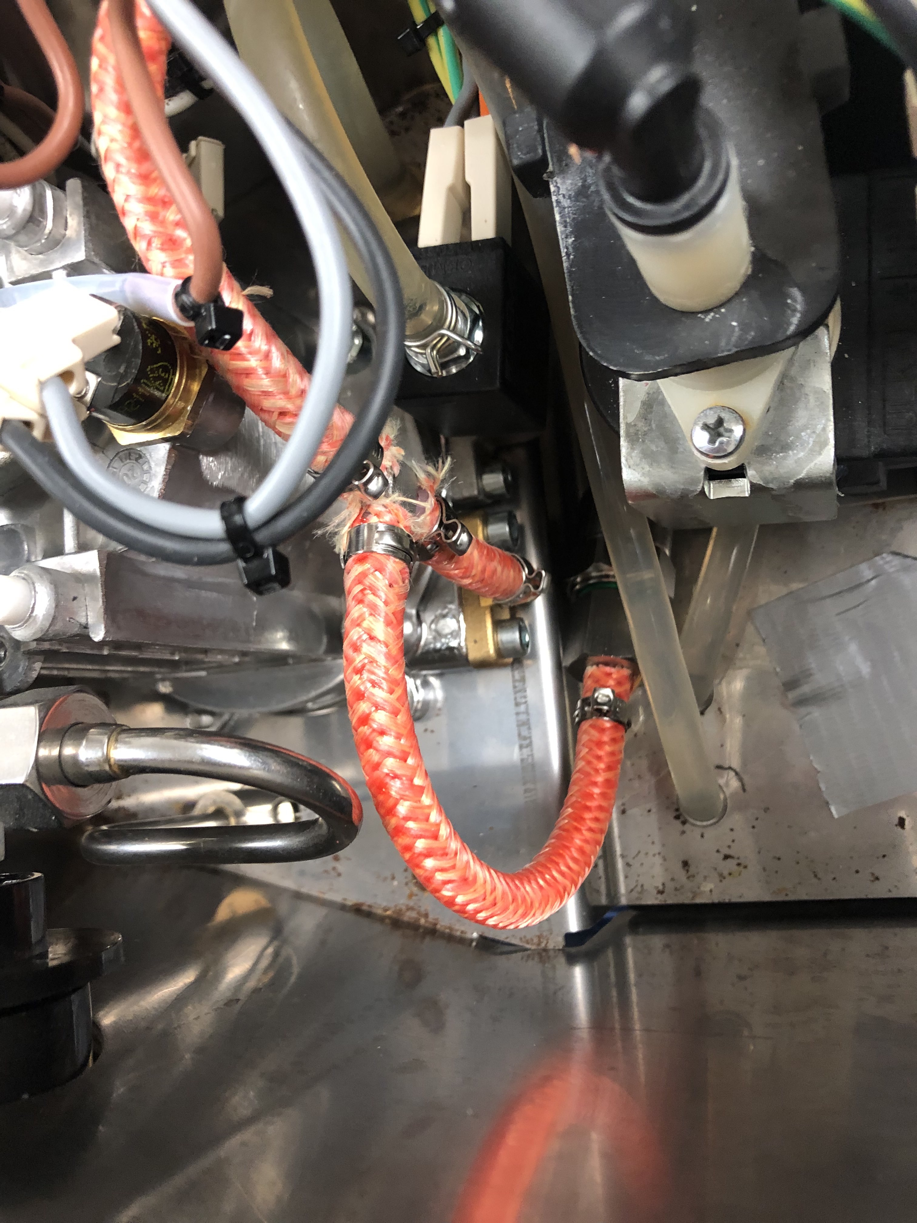
Inside the machine cut the hose between the pump and the boiler in a convenient location. Remember to slide the hose clamps onto the hose before adding the T fitting of the pressure sensor assembly. Crimp the T fitting. Lay the pressure sensor somewhere out of the way at the bottom of the machine.
Temperature Sensor
The thermocouple probe is installed at the bottom of the boiler on the left side, in place of the old brew thermostat. Unplug the thermostat and carefully unscrew it, as the threads are small and delicate. You may need to add thermal paste to the new thermocouple threads before gently screwing it in. Be careful not to bend the wires as you twist it, and only screw it in hand tight.
Make a small jumper to bridge the old thermostat wires together. This is shown on the schematic as well. Route the thermocouple wire and the pressure sensor wire up to join the control box later.
PLACEHOLDER IMAGE OF THERMOCOUPLE IN MACHINE AND ALSO THE JUMPER WIRES ON THE THERMOCOUPLE
Control box
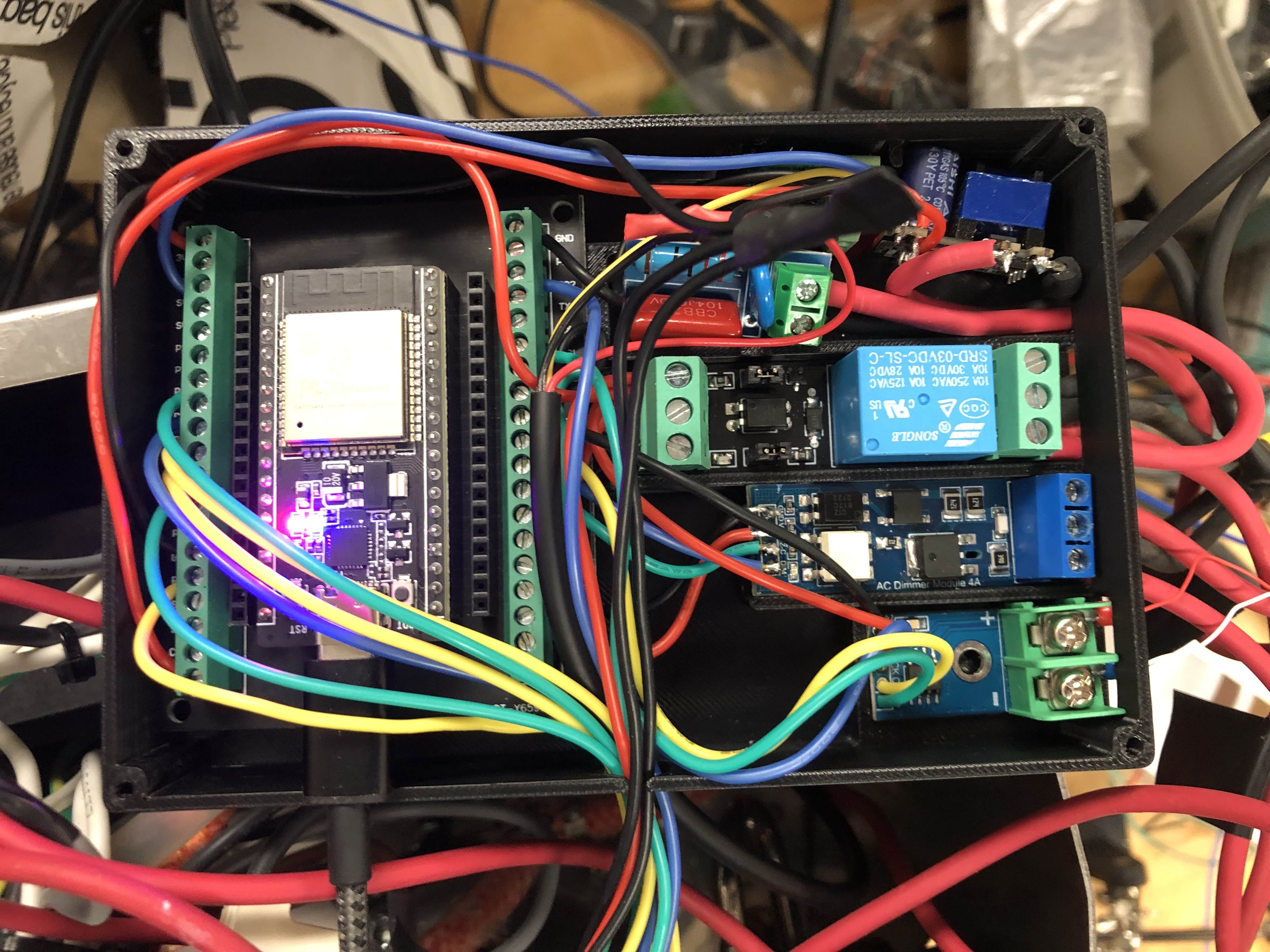
The control box houses the ESP-32 and the control electronics. Follow the schematic, the pictures, and the pins.h file to wire the components inside. Use small gauge silicone wire for these connections.
The grounds of all components are soldered together and wrapped in heat shrink. The 3.3V power from the ESP-32 is split to several components and is also soldered together and wrapped in heat shrink. Ideally all connections are either screw terminals or soldered, so desolder the pin headers and solder on the new connections as needed.
The low voltage wires to the screen and heater relay exit the box through the small hole at the bottom, and the high voltage wires all exit on the right side.
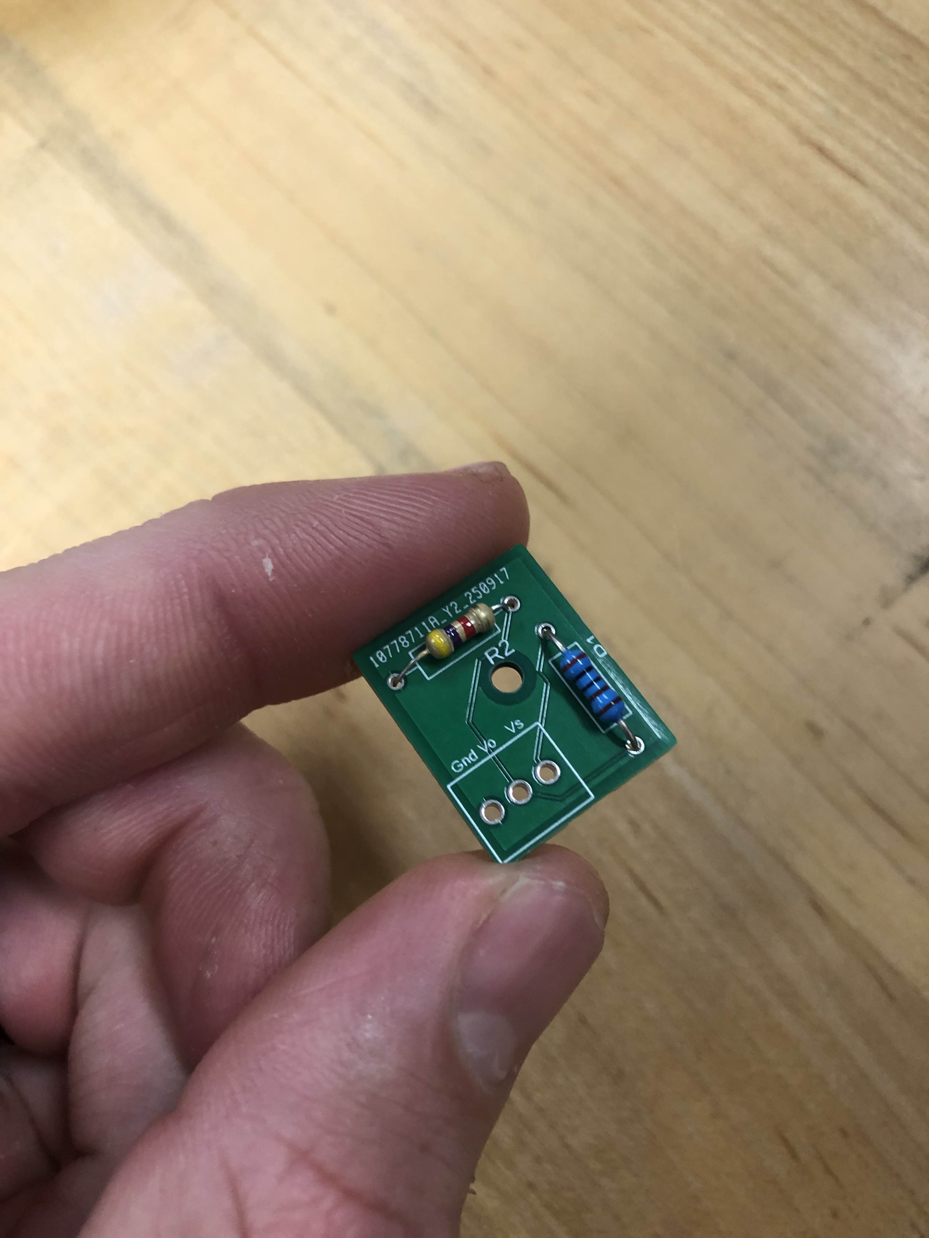
The pressure sensor works with a 5 volt source, so there is a voltage divider to step down to 3.3 volts for the ESP-32. Vs gets the signal pin of the pressure sensor, and Vo goes to the ADC pin of the ESP-32. This could also be made by soldering the resistors directly and wrapping in heat shrink, or on perf board.
Screen and Knob UI Box
The front UI box houses the screen and the rotary encoder knob. Route the wires out the machine through the gap by the water tank, and solder to the screen and knob as shown in the picture.
Use a small piece of foam to squish the screen in place while you close the lid. Epoxy the bar magnets to the back of the screen bracket so the UI box magnetically sticks to the screen.
PLACEHOLDER SCREEN PICTURE
High Voltage Wiring
This section explains the high voltage wiring very completely and this is totally not placeholder text.